Cavitation and flashing are both phenomena that can occur when a fluid passes through a control valve. They can be the source of unacceptable vibration, noise and damage.
When fluids pass through the control valve it introduces a restriction in the area of passthrough which will cause the velocity of the fluid to increase. When there is a pressure drop across the valve flashing and cavitation can occur.
1. Cavitation:
- Cavitation occurs when the pressure of the fluid drops below its vapor pressure, causing vapor bubbles to form in the liquid.
- In a control valve, as the fluid passes through a constriction (such as the valve orifice), the velocity increases, causing a decrease in pressure according to Bernoulli’s principle.
- If the pressure drops low enough, it can reach the vapor pressure of the fluid, causing it to vaporize and form bubbles.
- When these vapor bubbles move downstream and encounter higher pressure regions, they collapse violently (at high speed), causing damage to the valve components and potentially leading to erosion or noise and this is when most damage is done (when the bubbles collapse not when they are formed).
2. Flashing:
- Flashing is like cavitation but occurs when a fluid undergoes a phase change (from liquid to vapor – the beginning stage of cavitation) due to a drop in pressure.
- Unlike cavitation, where only vapor bubbles form, in flashing, the entire fluid may change phase.
- When the pressure of a liquid drops below its vapor pressure, it begins to vaporize, forming a two-phase mixture of liquid and vapor.
- This phase change can result in a sudden volume increase, which can lead to issues such as erosion, vibration, and noise in the valve and downstream piping.
Both cavitation and flashing can have detrimental effects on the performance and integrity of control valves and associated piping systems. They can lead to reduced efficiency, increased maintenance costs, and potential safety hazards. Engineers often take measures to mitigate these phenomena, such as proper valve sizing, selecting materials resistant to erosion, and using specific valve designs or control strategies to minimize pressure drops.
Detecting Cavitation
To detect cavitation, noise and vibration measurements could be used. A more general approach is to determine the cavitation index (sigma – σ), for the operating service conditions of the valve, as recommended by ISA 75: Where PU and PD are the upstream (inlet) and downstream (outlet) pressure and PV is the vapor pressure of the fluid through the control valve.
Using the cavitation index the existence and consequence of cavitation becomes ‘visible’:
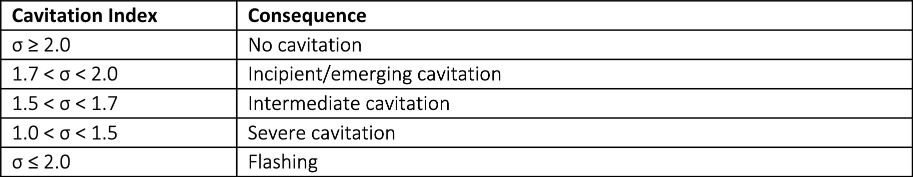 The cavitation index assumes that the size of the valve and the process fluid properties (other than vapor pressure) have little effect on the value of the index. In reality, the cavitation behaviour and cavitation coefficients are not independent or constant with either different upstream pressures or valve size.
The change in the value of a cavitation coefficient associated with the change in pressure is known as the “Pressure Scale Effect” (PSE). Likewise, the change in the value of a cavitation coefficient associated with valve size is known as the “Size Scale Effect” (SSE). In addition to direct valve size changes, the presence of pipe reducers or increasers can also affect the value of a coefficient of the index. Other influencers are the viscosity, density and surface tension of the fluid passing through the valve. These do not change the cavitation index but change the degree of cavitation at a particular level.
To have a continuous insight into the existence of cavitation onboard with the Control Valve App today. On the basis of the data you already store in your process historians you gain immediate insights on the service life of your control valves!