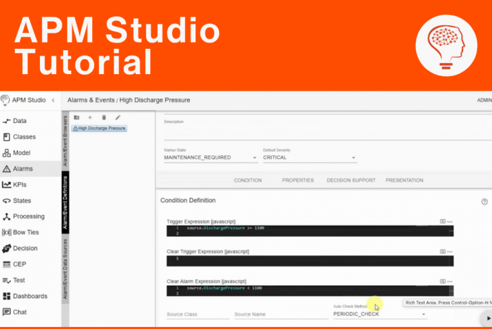
This short tutorial shows how you set-up a Modbus TCP Master connection to a Modbus TCP Slave. The tutorial uses the Modbus Simulator for RS-232 and TCP/IP.
The tutorial shows:
- The creation of a Data Definition;
- The configuration of the Modbus TCP Connection; and
- The configuration of IO-points, coil/discreteInput/holdingRegister and inputRegister, reading values from the Modbus Simulator.
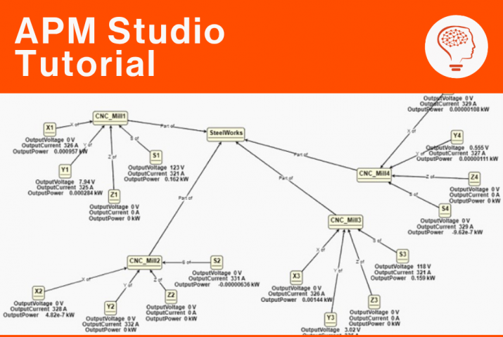
As data flows from the Modbus Slave into APM Studio it is mapped, using specific Mapping, to an object.
Background information
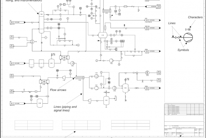
The Modbus protocol is a widely used communication protocol in industrial automation and control systems. It was developed in 1979 by Modicon (now Schneider Electric) for use with programmable logic controllers (PLCs). It enables communication between various devices connected to the same network, such as sensors, actuators, controllers, and computers.
The key features of Modbus are:
- Master-Slave (RTU) or Client-Server (TCP) Architecture:
– A Master (or Client) initiates requests, and a Slave (or Server) responds.
– Multiple slave devices can be connected to a single master. - Simple and Efficient:
– Uses simple request-response messaging.
– Lightweight and easy to implement. - Supports Multiple Physical Layers:
– Modbus RTU (Binary format over RS-485/RS-232)
– Modbus ASCII (Readable text format over serial)
– Modbus TCP/IP (Ethernet-based communication) - Registers and Data Types:
– Uses a structured addressing scheme with coils (binary outputs), discrete inputs, holding registers (read/write data), and input registers (read-only data). - Widely Used in Industrial Applications:
– SCADA (Supervisory Control and Data Acquisition)
– Industrial IoT (IIoT)
– Energy management systems
– Building automation
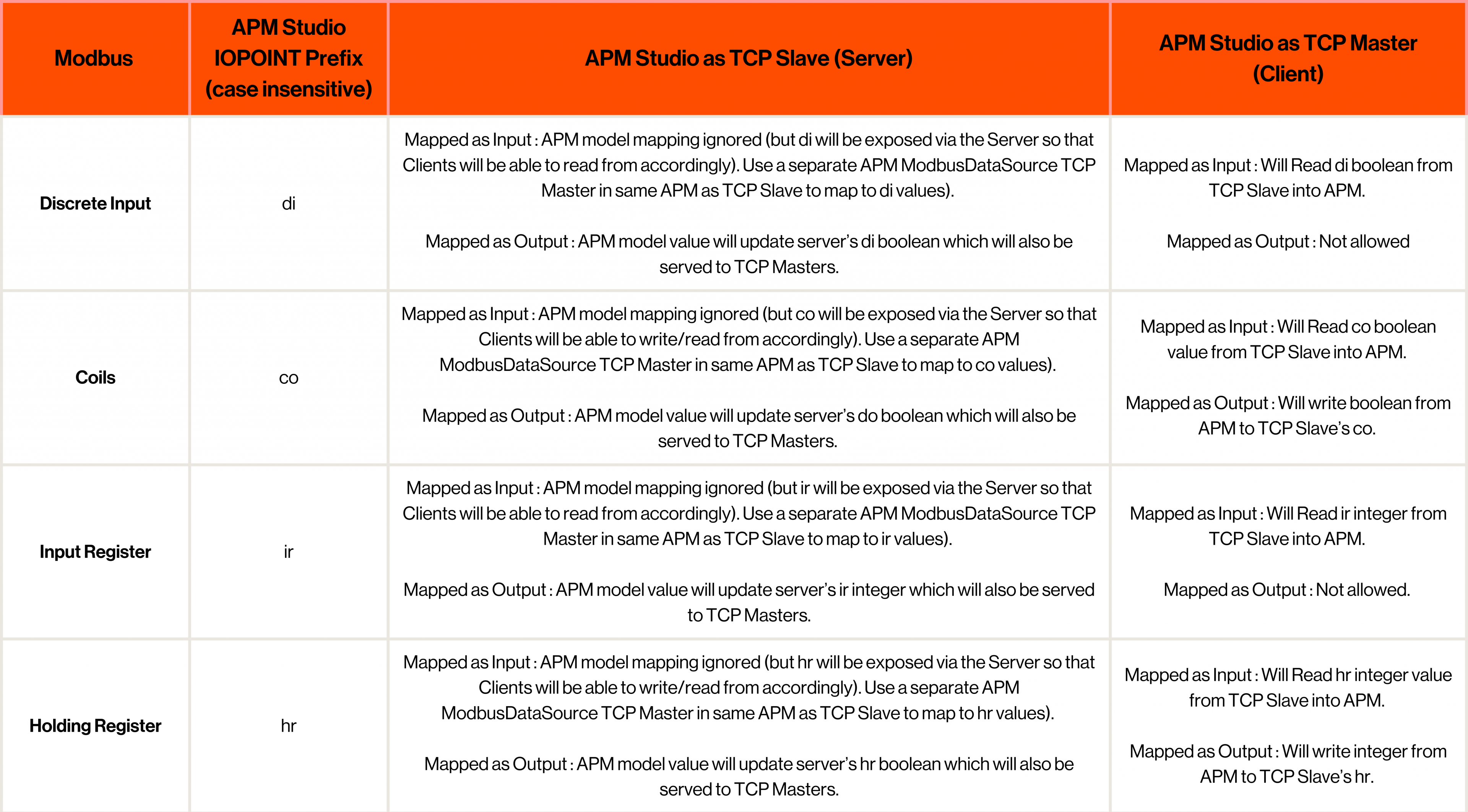
Modbus supports the following types of IO per its specification:
- Discrete Input | Read Only
- Coils | Read / Write
- Input Registers | Read Only
- Holding Registers | Read / Write
In APM Studio these are mapped in the following ways:
Want expert guidance for your APM Studio configuration?
Book a call with Artur Loorpuu, Senior Solutions Engineer in Digitalization. Artur specialises in turning industrial challenges into practical digital solutions through expertise in predictive maintenance, digital twins, data science, and strategic product management.
Let’s explore how we can support your goals!